I. scheme description
Shr5000 wind farm booster station integrated automation system can conduct real-time monitoring and control of fans, converter boxes and other equipment in the wind farm booster station, realize equipment data collection, analysis, processing, event recording and storage, and present the operation of the station through various types of charts, trends and reports, so as to ensure the remote monitoring needs of customers for the data of the power station. Its friendly user interface, comprehensive data service, powerful analysis function and perfect fault alarm ensure the safe, reliable and stable operation of the wind farm power generation system.
II. Scheme features
Function overall optimization design
The system provides perfect relay protection, measurement, local monitoring and telecontrol functions, and systematically optimizes the functions of voltage and reactive power control (VQC), five prevention, small current grounding line selection, equipment operation and management.
The system includes the active / reactive power automatic control system of the wind farm, which is based on the unified monitoring platform. The system receives the regulation target issued by the dispatching master station regularly or the local predetermined regulation target to calculate the power demand of the wind farm, selects the control equipment and distributes the power, and automatically issues the final control command to the controlled equipment;
The system provides wind power prediction system, which can accurately predict the power change curve of the wind farm in the next 168 hours. The short-term prediction accuracy of the system is more than 80%, and the ultra short-term prediction accuracy is more than 90%.
The system integrates the five defense functions and can be seamlessly connected with the five defense systems of other mainstream manufacturers.
Powerful and flexible means of communication
the network of station control layer and bay layer supports 100M Ethernet structure to realize high-speed and bottleneck free data transmission;
Adopt IEC61850 or IEC60870-5-103 standard transmission protocol to ensure the openness of the system;
The communication protocol is rich in variety and can be extended according to the engineering requirements;
The communication network structure has high reliability and strong expansibility, which can meet the requirements of various network structures, such as dual network redundancy, fiber star topology and fiber ring network.
Open background software system
The background system adopts a flexible architecture of hierarchical design, modular packaging and application configuration on demand. The application program and database can be flexibly configured on each computer node.
The background system supports mixed deployment and can be composed of computers with different operating systems installed. The system function can be expanded conveniently according to the user's needs, and meet the user's requirements for flexibility and scalability to the greatest extent.
Integrated design of real-time database and commercial database. It supports a variety of commercial databases and has the capabilities of dual computers, dual networks and dual databases, providing high reliability guarantee for historical data storage and access;
fully support IEC61850 standard, establish complete primary and secondary models of plant and station through advanced integrated modeling of diagram and module and visualization.
Safe and reliable relay protection and measurement and control device
the communication protocol and information model of the protection and measurement and control device conform to IEC 61850 or 103 standards; it is compatible with intelligent and conventional primary equipment; it supports iec61588, IRIG-B or second pulse timing, and the timing accuracy can reach 1 μ s;
The modular design is adopted for the device, and special configuration tools can be used to configure various protection functions according to different requirements, so the function adjustment is convenient.
III. typical system configuration

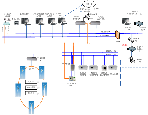
Note: for 110kV and below voltage level substation, the network can be simplified according to the needs, and the equipment is not divided into small rooms.
Station control layer equipment includes monitoring host, five prevention workstation, AGC \ AVC control host, telecontrol manager, GPS clock synchronization equipment; bay layer equipment includes protection measurement and control device of each bay or equipment, standby automatic switching device, bus protection device, low-voltage Bay protection measurement and control device, anti Island device, phasor measurement device, etc.
A set of master clock is set in the station, with GPS and Beidou satellite as the standard clock source. SNTP network timing mode is adopted for station control layer equipment, and IRIG-B code timing is adopted for Bay layer equipment.
According to the requirements of voltage level and equipment interval configuration, different application configurations can be made according to single set configuration and double set configuration.
AGC \ AVC system is deployed in the safety I area of the electric field and adopts the design of dual machine hot standby. The system communicates with the monitoring system, reactive compensation device and other equipment of the wind farm booster station to obtain the operation information of the fan, reactive compensation device, booster station network, main transformer tap, switch, knife gate, etc.; communicates with the wind power prediction system to obtain the information of ultra short-term prediction of active power, adjustable capacity, predicted wind speed, etc.; communicates with the dispatching master station to receive the active power issued by the dispatching. , reactive power regulation instruction, which is processed and calculated by the control strategy according to the collected field information, is issued to remotely regulate and control the active power, reactive power, main transformer tap gear, reactive power of reactive compensation device, etc.
The wind power prediction system is deployed in safety zone II. By collecting the data of numerical weather forecast, wind turbine monitoring data, wind tower data and booster station, the short-term power prediction and ultra short-term power prediction of the wind farm are completed, and the wind tower and power prediction data are uploaded to the grid side.


